Two pneumatic valves with the same connection thread do not necessarily deliver the same flow. The port describes how the component connects to the circuit. Internal passages, valve function and the conditions behind the flow rating determine a different part of the selection.
Read the test conditions with the number
Festo’s HE technical data lists connection sizes separately from nominal flow, sonic conductance and the critical pressure-ratio parameter. It also states the pressure conditions used for its nominal-flow values. Those details are part of the rating, not optional footnotes.
Compare valves on a common basis. Check whether flow is expressed as a standardized volume, which reference conditions apply and what inlet and outlet pressures were used. A number measured with a different pressure drop is not automatically a like-for-like alternative.
Include the mounting arrangement
Festo’s ISO 5599-1 documentation distinguishes flow through the valve from flow in individual sub-base and linked arrangements. That provides a useful reminder: the component’s headline value may not describe the assembled path the machine will use.
Request the data for the exact valve function, mounting base and supply arrangement being quoted. Include fittings, tubing, exhaust treatment and other components in the circuit review. Improving one component may leave the controlling restriction elsewhere.
| Item to compare | Information needed |
|---|---|
| Connection | Thread type, size and mounting interface |
| Flow rating | Units, reference conditions and pressure basis |
| Installed assembly | Valve function, sub-base or manifold arrangement |
| Dynamic requirement | Required response under the intended machine load |
Tie selection to the actual task
For a replacement review, document the required operating pressure, air quality, valve function and electrical or pilot interface as well as the flow requirement. The same port size does not establish interchangeability across these characteristics.
Ask the supplier to show that its proposed assembly meets the required machine response without relying on an unspecified pressure increase. If testing is needed, use the intended circuit and record the conditions so the result can be reproduced.
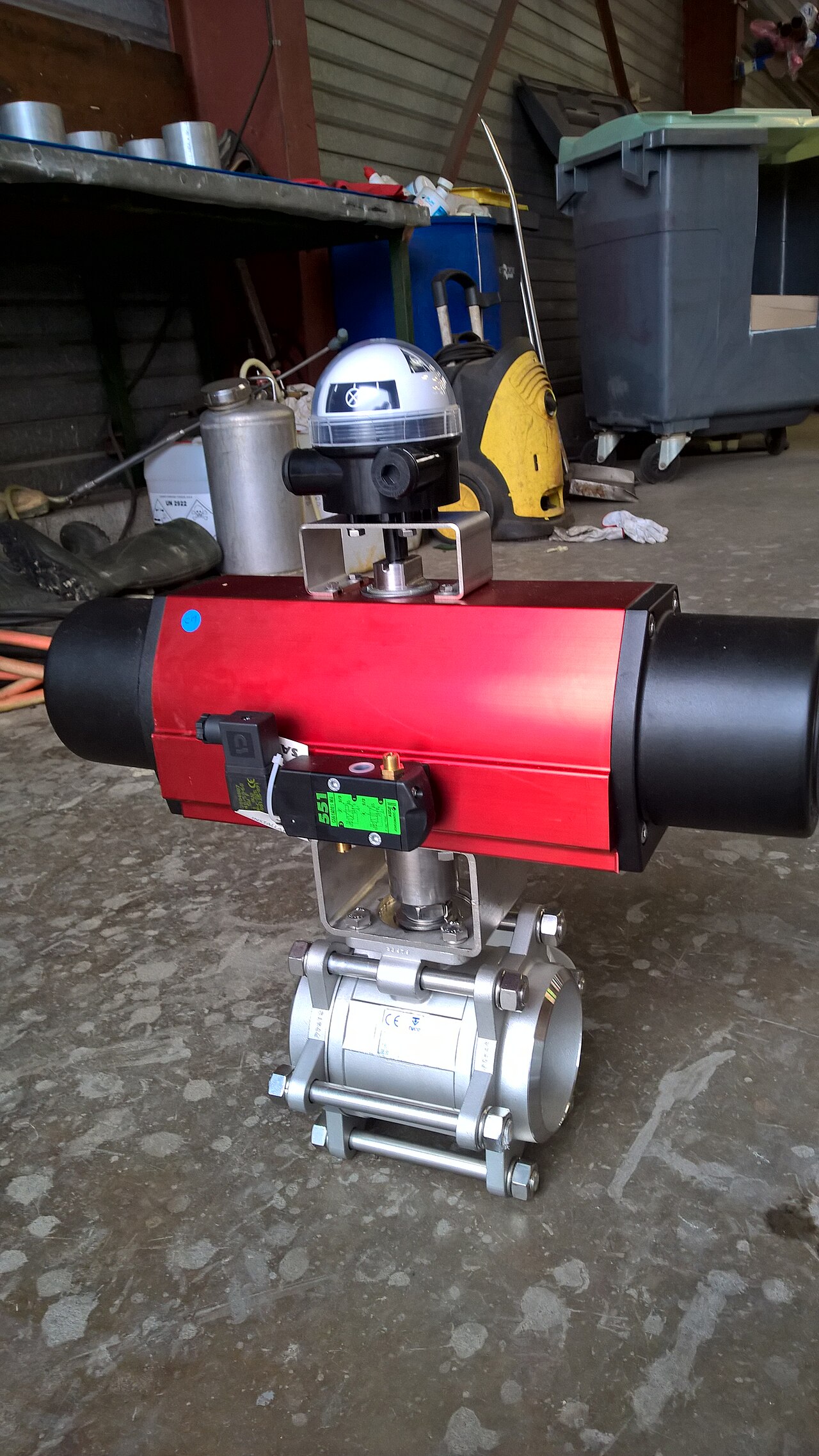
The photograph shows a solenoid control valve on a pneumatic actuator. It illustrates a real control interface and does not identify the flow capacity or function of either Festo product family discussed in the source documents.