A flexible coupling provides useful tolerance for movement between connected shafts. Its maximum published displacement is still a limit to interpret, rather than an installation target to aim for. The machinery and the coupling need a common alignment plan.
Identify the kind of movement
Angular misalignment describes shafts whose centerlines meet at an angle. Radial, or parallel, offset describes separated centerlines. Axial movement changes the relative position along the shafts. Real machinery may experience more than one at the same time.
The Lovejoy curved-jaw catalog lists these displacement types and relates its data to operating conditions. It specifically links careful alignment with elastomer life. A catalog’s accommodation capability therefore does not remove the reason to install the drive accurately.
Read the full operating envelope
Check the exact coupling size, elastomer, speed, torque and temperature basis. Do not combine separate maximum displacement values unless the manufacturer explicitly allows that combination. Ask for the relevant selection or derating method when several displacements occur together.
KTR’s drive-technology catalog likewise treats coupling selection and alignment as connected engineering tasks. Thermal movement and the behavior of the connected machines belong in the review, particularly where the cold installation position differs from the operating position.
For procurement, request an explicit answer to three questions:
- What alignment tolerance applies to this installed machine combination?
- What operating movement has been allowed for in the coupling selection?
- How will the cold measurements and any thermal-growth target be recorded?
Keep selection and installation records connected
For example, replacing a spider with a different hardness may change more than a maintenance part number. Before accepting a substitution, check the specified torque capability and other relevant coupling characteristics with the supplier. The existing alignment record should remain attached to the machine, rather than disappearing into a separate purchasing file.
Physical checks require isolated machinery and the manufacturer’s installation procedure. After assembly, restore guarding and verify operation through the approved commissioning process.
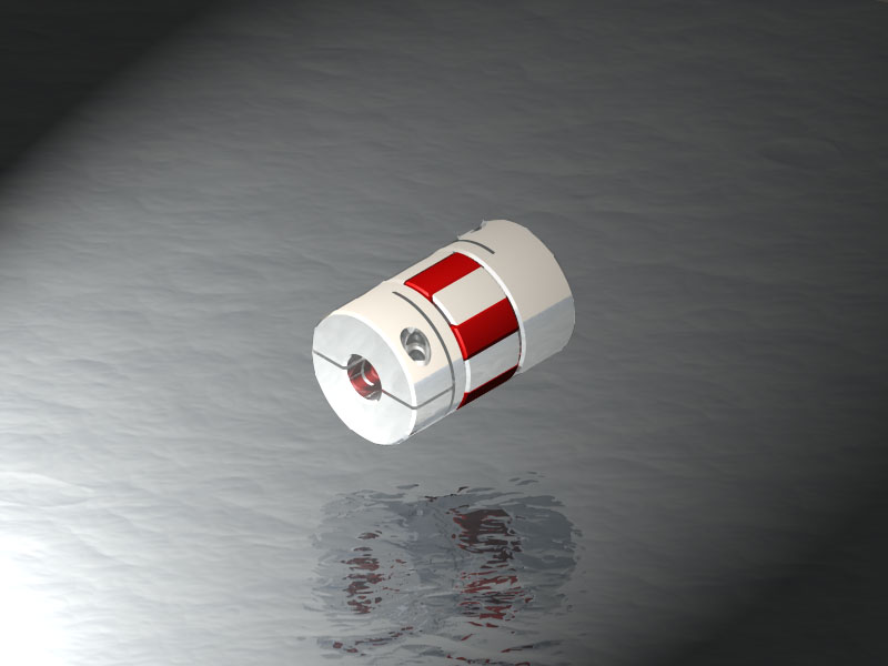
The cover is a computer illustration of a jaw coupling, not a photograph of a diagnosed failure. In an actual maintenance investigation, document the installed component, measured alignment and observed condition separately. A worn elastomer alone does not establish which operating condition caused the wear.